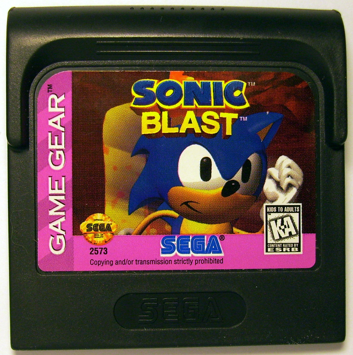
Game Gear Cartridge Pinout
Posted By admin On 09/05/18Several different revisions of Game Gear main PCBs were created, and there may be more to be found. The two smaller PCBs located in the rear half of the case appear. Leap Office 2000 For Windows 7 64 Bit. 8M-Bit (1MByte) SEGA GAME GEAR Flash Cartridge. According to the provided pinout diagrams (Links Below); you will not have any problems.

Available at Sega. Pinout 45 1 44 2 +---------------+ (at the cartridge) Pin Dir Name Description 1 +34V Liquid drive? 2 +5V Power +5V 3 /WR Write 4 A12 Address bit12 5 A7/CL1B3 Address bit7 6 A6/CL1A2 Address bit6 7 A5/CL1B2 Address bit5 8 A4/CL1A1 Address bit4 9 A3/CL1B1 Address bit3 10 A2/DW Address bit2 11 A1/DO3 Address bit1 12 A0/DO1 Address bit0 13 D0/DB Data bit0 14 D1/P3 Data bit1 15 D2/P2 Data bit2 16 GND D Ground (Digital) 17 GND A Ground (Analog) 18 GND D Ground (Digital) 19 D3/P4 Data bit3 20 D4/P1 Data bit4 21 D5/CL2 Data bit5 22 D6/DO2 Data bit6 23 D7/DO4 Data bit7 24? /MREQ Memory Request (Cartridge Output Enable) 25 A10/TPR2 Address bit10 26 /RD Read signal 27? /M0-7 Memory 0000h-7FFFh 28 A15 Address bit15 29 A11 Address bit11 30 A9/TPR1 Address bit9 31 A8/CLIA3 Address bit8 32 A13 Address bit13 33 A14 Address bit14 34? /M8-B Memory 8000h-B000h 35 +5V Power +5V 36? /M1 M1 Cycle 37?

I/O Request 38? /RFSH Refresh 39? /RESET Reset 40? Clock 41 GND Ground 42 /GG MS/GG Video (zoomed mode) 43 /TV TV Cartridge Signal In 44 TVSNDR TV Sound R 45 TVSNDL TV Sound L Note: Direction is Console relative Cartridge Note: / = Active Low Sources • •.